在使用GEF進(jìn)行開(kāi)發(fā)的時(shí)候,對(duì)于需要繪制的圖形的節(jié)點(diǎn),往往除了模型對(duì)象本身之外,還需要有一個(gè)相應(yīng)的“圖”對(duì)象來(lái)保存圖中這個(gè)節(jié)點(diǎn)的位置,以及大小等圖相關(guān),但是與業(yè)務(wù)模型無(wú)關(guān)的一個(gè)對(duì)象。而在一開(kāi)始希望顯示一個(gè)初始模型文件的時(shí)候,再對(duì)應(yīng)保存圖信息的文件不存在的情況下,如何能夠很好的顯示這個(gè)圖,是一個(gè)比較麻煩的問(wèn)題,涉及到對(duì)布局算法的一些分析與實(shí)現(xiàn)。這片文章就是介紹,如何使用GEF內(nèi)的DirectedGraph這個(gè)類以及其相應(yīng)的布局算法類DirectedGraphLayout,來(lái)解決這個(gè)問(wèn)題。
基本思想是:為GEF的EditPart模型生成一個(gè)DirectedGraph,然后使用DirectedGraphLayout來(lái)計(jì)算布局,最后將布局的結(jié)果通過(guò)GEF顯示出來(lái)。
在參考了GEF的flow example之后,對(duì)其代碼作了部分重構(gòu),寫了這片文章,希望對(duì)遇到同樣問(wèn)題的同志能夠有一定的幫助。
首先引入一個(gè)接口:
public interface GraphBuilder {
public void contributeNodesToGraph(DirectedGraph graph, Map map);
public void contributeEdgesToGraph(DirectedGraph graph, Map map);
public void applyGraphResults(DirectedGraph graph, Map map);
}
這個(gè)接口中定義了幾個(gè)方法,其含義從其方法名中可以猜出:
contributeNodesToGraph:將當(dāng)前對(duì)象作為節(jié)點(diǎn)(Node)添加到DirectedGraph中。
contributeEdgesToGraph:將當(dāng)前對(duì)象所對(duì)應(yīng)的連線作為邊(Edge)添加到DirectedGraph中。
applyGraphResults:將圖中生成的布局信息取出,對(duì)本對(duì)象進(jìn)行重新布局。
接口中的graph參數(shù)就是保存的圖的信息,map參數(shù)維持一個(gè)對(duì)象到節(jié)點(diǎn)/邊的映射,使得每個(gè)對(duì)象能夠方便的找到其對(duì)應(yīng)的圖中的節(jié)點(diǎn)或者邊。這個(gè)接口的使用,在后面會(huì)有涉及。下面先看看顯示圖的容器是如何構(gòu)建的。
圖的容器定義為GraphDiagramEditPart,這個(gè)EditPart對(duì)應(yīng)于要顯示的有向圖的容器。它實(shí)現(xiàn)了GraphBuider接口,這也是我們主要需要關(guān)注的接口:
public class GraphDiagramEditPart extends AbstractGraphicalEditPart implements
GraphBuilder.
contributeNodesToGraph方法將自身作為節(jié)點(diǎn)添加到圖中,但是因?yàn)?/SPAN>GraphDiagramEditPart對(duì)應(yīng)的是容器,因此它不需要向圖中添加信息,只是調(diào)用其子EditPart,將其添加到圖中。
public void contributeNodesToGraph(DirectedGraph graph, Map map) {
for (int i = 0; i < getChildren().size(); i++) {
NodeEditPart activity = (NodeEditPart)getChildren().get(i);
activity.contributeNodesToGraph(graph, map);
}
}
contributeEdgesToGraph方法將這個(gè)EditPart的所有子EditPart取出,調(diào)用其contributeEdgesToGraph方法,通過(guò)這個(gè)方法,就可以將所有的邊添加到圖中了:
public void contributeEdgesToGraph(DirectedGraph graph, Map map) {
for (int i = 0; i < getChildren().size(); i++) {
NodeEditPart child = (NodeEditPart)children.get(i);
child.contributeEdgesToGraph(graph, map);
}
}
applyGraphResults方法將所有取出所有的子EditPart,并調(diào)用其applyGraphResults,使得圖中所生成的布局信息能夠被應(yīng)用到顯示上。
public void applyGraphResults(DirectedGraph graph, Map map) {
applyChildrenResults(graph, map);
}
protected void applyChildrenResults(DirectedGraph graph, Map map) {
for (int i = 0; i < getChildren().size(); i++) {
GraphBuilder part = (GraphBuilder) getChildren().get(i);
part.applyGraphResults(graph, map);
}
}
下面要介紹的是NodeEditPart,它作圖中所有節(jié)點(diǎn)所對(duì)應(yīng)的EditPart的抽象父類,也實(shí)現(xiàn)了GraphBuilder接口。每一個(gè)要做為節(jié)點(diǎn)添加到圖中的EditPart,應(yīng)該繼承這個(gè)類。
public abstract class NodeEditPart extends AbstractGraphicalEditPart implements
GraphBuilder{
public void contributeNodesToGraph(DirectedGraph graph,
Map map) {
Node n = new Node(this);
n.outgoingOffset = 7;
n.incomingOffset = 7;
n.width = getFigure().getPreferredSize().width;
n.height = getFigure().getPreferredSize().height;
n.setPadding(new Insets(10,8,10,12));
map.put(this, n);
graph.nodes.add(n);
}
public void contributeEdgesToGraph(DirectedGraph graph, Map map) {
List outgoing = getSourceConnections();
for (int i = 0; i < outgoing.size(); i++) {
EdgeEditPart part = (EdgeEditPart)getSourceConnections().get(i);
part.contributeEdgesToGraph(graph, map);
}
}
public void applyGraphResults(DirectedGraph graph, Map map) {
Node n = (Node)map.get(this);
getFigure().setBounds(new Rectangle(n.x, n.y, n.width, n.height));
for (int i = 0; i < getSourceConnections().size(); i++) {
EdgeEditPart trans = (EdgeEditPart) getSourceConnections().get(i);
trans.applyGraphResults(graph, map);
}
}
}
再就是邊所對(duì)應(yīng)EditPart的抽象類EdgeEditPart。每一個(gè)要作為邊添加到圖中的EditPart,需要繼承這個(gè)類。在上面NodeEditPart中對(duì)其所對(duì)應(yīng)的Figure其實(shí)并沒(méi)有什么要求,但是對(duì)EdgeEditPart所對(duì)應(yīng)的Figure,要求其Figure必須由一個(gè)BendpointConnectionRouter,作為其ConnectionRouter:setConnectionRouter(new BendpointConnectionRouter())。這樣圖的邊的路徑信息才能夠被顯示出來(lái)。
public abstract class EdgeEditPart extends AbstractConnectionEditPart implements
GraphBuilder {
public void contributeEdgesToGraph(DirectedGraph graph, Map map) {
Node source = (Node)map.get(getSource());
Node target = (Node)map.get(getTarget());
Edge e = new Edge(this, source, target);
e.weight = 2;
graph.edges.add(e);
map.put(this, e);
}
public void applyGraphResults(DirectedGraph graph, Map map) {
Edge e = (Edge)map.get(this);
NodeList nodes = e.vNodes;
PolylineConnection conn = (PolylineConnection)getConnectionFigure();
conn.setTargetDecoration(new PolygonDecoration());
if (nodes != null) {
List bends = new ArrayList();
for (int i = 0; i < nodes.size(); i++) {
Node vn = nodes.getNode(i);
int x = vn.x;
int y = vn.y;
if (e.isFeedback) {
bends.add(new AbsoluteBendpoint(x, y + vn.height));
bends.add(new AbsoluteBendpoint(x, y));
} else {
bends.add(new AbsoluteBendpoint(x, y));
bends.add(new AbsoluteBendpoint(x, y + vn.height));
}
}
conn.setRoutingConstraint(bends);
} else {
conn.setRoutingConstraint(Collections.EMPTY_LIST);
}
}
}
最后的就是一個(gè)LayoutManager來(lái)初始化圖的創(chuàng)建,以及對(duì)圖的信息進(jìn)行解釋了,生成最終布局了。這個(gè)GraphLayoutManager作為GraphDiagramEditPart所對(duì)應(yīng)的GraphDiagram的LayoutManager,來(lái)顯示圖的內(nèi)容。
public class GraphLayoutManager extends AbstractLayout {
private GraphBuilder diagram;
GraphLayoutManager(GraphBuilder diagram) {
this.diagram = diagram;
}
protected Dimension calculatePreferredSize(IFigure container, int wHint,
int hHint) {
container.validate();
List children = container.getChildren();
Rectangle result = new Rectangle().setLocation(container
.getClientArea().getLocation());
for (int i = 0; i < children.size(); i++)
result.union(((IFigure) children.get(i)).getBounds());
result.resize(container.getInsets().getWidth(), container.getInsets()
.getHeight());
return result.getSize();
}
public void layout(IFigure container) {
DirectedGraph graph = new DirectedGraph();
Map partsToNodes = new HashMap();
diagram.contributeNodesToGraph(graph, partsToNodes);
diagram.contributeEdgesToGraph(graph, partsToNodes);
new DirectedGraphLayout().visit(graph);
diagram.applyGraphResults(graph, partsToNodes);
}
}
可以看到在layout方法中,首先生成了一個(gè)DirectedGraph,并調(diào)用了contributeNodesToGraph以及contributeEdgesToGraph方法,將節(jié)點(diǎn)和邊的信息添加到這個(gè)生成的DirectedGraphGraph中,然后使用布局算法DirectedGraphLayout().visit(graph)來(lái)計(jì)算生成圖的信息(這里使用了visitor模式)最后調(diào)用applyGraphResults將圖的信息應(yīng)用到圖形的顯示上。
至此,所有框架的工作做完了,如果要將模型作為一個(gè)有向圖顯示的話,只需要將模型的容器對(duì)象對(duì)應(yīng)于GraphDiagramEditPart(在EditPartFactory中進(jìn)行映射),為每一個(gè)需要表示為節(jié)點(diǎn)的對(duì)象,對(duì)應(yīng)到一個(gè)繼承于NodeEditPart的EditPart,為每一個(gè)需要表示為邊的模型對(duì)象,對(duì)應(yīng)到一個(gè)繼承于EdgeEditPart的EditPart。這樣,就能夠?qū)D的布局算法,應(yīng)用到GEF框架中了。
這里寫的比較簡(jiǎn)單,使用起來(lái)也會(huì)有一些具體的約束。例如在有向圖中,是不能夠有孤立的節(jié)點(diǎn)的。如果使用CompoundDirectedGraph,就不會(huì)有這樣的問(wèn)題,CompoundDirectedGraph可以包括子圖,可以支持更為復(fù)雜的圖形。在Flow Example中使用的就是CompoundDirectedGraph。在后面,我或許會(huì)將這個(gè)框架進(jìn)行改寫,以使其支持CompoundDirectedGraph來(lái)進(jìn)行布局算法。下面的圖是一個(gè)生成的例子,大家可以看一下效果:
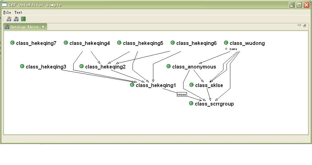
這是從OWL文件中讀取內(nèi)容之后生成的一個(gè)圖的表示。可以看到,OWL的節(jié)點(diǎn)通過(guò)自動(dòng)圖的自動(dòng)布局之后,已經(jīng)有了較好的視覺(jué)效果。如果沒(méi)有這樣的布局的話,因?yàn)閱渭兊腛WL文件中并不會(huì)包含節(jié)點(diǎn)的圖的信息,圖顯示出來(lái)會(huì)變得非常的亂,所有的節(jié)點(diǎn)都會(huì)堆在一起。